CALL US

+1-714-842-3330

GLOSSARY

Still have questions?

Use this contact form to get in touch with us!

This information is provided to help clarify and define the terminology associated with Vanguard products and their applications. Some of these terms are listed in the component datasheets. These terms describe issues associated with product design and performance, materials and theory and applications. A thorough understanding of these terms and definitions will aid in selling, procurement and application of Vanguard products.

Definitions

A

The term “air core coil” describes an inductor that does not use a magnetic core made of a ferromagnetic material. The coils are wound on plastic, ceramic, or other nonmagnetic forms, as well as those that actually have air inside the windings.

The temperature of still air immediately surrounding a component or circuit. A typical method to measure ambient temperature is to record the temperature that is approximately 1/2 inch from the body of the component or circuit.

The relative decrease in amplitude of a given parameter. Attenuation measurements are common for voltage, current and power. It is usually expressed in units of decibels (dB).

For a power ratio, one dB = 10 Log10 (P1/P2).

A dB is equal to 20 Log20 (I1/I2) for current and 20 Log10 (V1/V2) for voltage ratios.

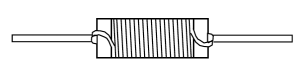
An inductor constructed on a core with concentric leads on opposite ends of the core. Axial inductors are available for both power applications and RF applications, and are available in many core materials including the basic phenolic, ferrite and powdered iron types. Both rod and bobbin shapes are utilized. Axial inductors are very suitable for tape and reel packaging for auto placement. (see Inductor)

B

A core with the shape of a bobbin or spool which contains flanges. Bobbin cores are available with and without leads and in the axial and radial form. (see Axial Inductor and Radial Inductor)

Radial Leaded
Leadless
Axial Leaded

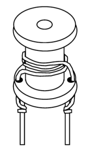
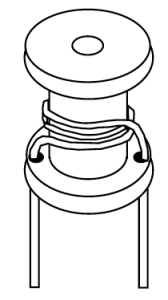
Bobbin wound inductors refers to a type or method of construction of winding inductors chokes and reactors. Toroidal coils are wound directly onto a toroidal core. The core may be coated or boxed to insulate it from the coil windings. In contrast, bobbin wound inductor coils are wound independently of the core. The coil must hold its shape or form until the coil is assembled onto the inductor core. One common method of doing this is to wind the coil onto a bobbin (also referred to as a spool), hence the term “bobbin wound winding inductor”.

C

Ceramic is one of the common materials used for inductor cores. Its main purpose is to provide a form for the coil. In some designs it also provides the structure to hold the terminals in place. Ceramic has a very low thermal coefficient of expansion. This allows for relatively high inductance stability over the operating temperature ranges. Ceramic has no magnetic properties. Thus, there is no increase in permeability due to the core material.

Ceramic core inductors are often referred to as “air core” inductors. Ceramic core inductors are most often used in high frequency applications where low inductance values, very low core losses and high Q values are required.

Another common name for inductors. (see Inductor)

A common mode choke is a passive electromagnetic device that filters out the unwanted high-frequency noise signal from external sources or other circuits of the system while allowing the desired DC or low-frequency signal to pass. A CMC uses two coils wound on a single core to suppress interference and prevent signal pollution.

Material placed within and around a coil to support the coil and to play a role in the magnetic flux properties of the inductor.

Core losses are caused by an alternating magnetic field in the core material. The losses are a function of the operating frequency and the total magnetic flux swing. The total core losses are made up of three main components: Hysteresis, eddy current and residual losses. These losses vary considerably from one magnetic material to another. Applications such as higher power and higher frequency switching regulators and RF designs require careful core selection to yield the highest inductor performance by keeping the core losses to a minimum.

The maximum current the inductor can handle at the rated temperature range. Expressed in milliamps (mA) or amps (A) maximum.

D

The unidirectional flow or movement of electric charge carriers. The intensity of the current can vary with time, but the general direction of movement stays the same at all times.

The resistance of the inductor winding measured with no alternating current. The DCR is most often minimized in the design of an inductor. The unit of measure is ohms (Ω), and it is usually specified as a maximum rating. This is an undesirable characteristic, which is a by-product of the wire or conductive material used. The lower the DCR, the more current an inductor will handle.

E

Inductors that have been coated with epoxy as opposed to having a molded case, shrink wrapped tubing or left with an open construction body. Epoxy coated inductors typically have smooth edges and surfaces. The epoxy coat acts as an insulation. Both radial and axial styles can be found with epoxy coated surfaces.

F

Ferrite is a magnetic material which consists of a mixed oxide of iron and other elements that are made to have a crystalline molecular structure. The crystalline structure is created by firing the ferrite material at a very high temperature for a specified amount of time and profile. The general composition of ferrites is xxFe2O4 where xx represents one of several metals. The most popular metal combinations are manganese and zinc (MnZn) and nickel and zinc (NiZn). These metals can be easily magnetized.

Common circuit design for low power (<100 Watts) switch mode power supply.

Used in a flyback power supply. Also called horizontal output transformer.

Range of frequencies over which the inductor is expected to operate.

I

The property of a circuit element which tends to oppose any change in the current flowing through it. The inductance for a given inductor is influenced by the core material, core shape and size, the turns count and the shape of the coil. Inductors most often have their inductances expressed in microhenries (µH). The following table can be used to convert units of inductance to microhenries. Thus, 47 mH would be equal to 47,000 µH.

1 henry (H) = 106 µH
1 millihenry (mH) = 103 µH
1 microhenry (µH) = 1 µH
1 nanohenry (nH) = 10-3 µH

Standard inductance tolerances are typically designated by a tolerance letter. Standard inductance tolerance letters include:

LetterTolerance
F± 1%
G± 2%
H± 3%
J± 5%
K± 10%
L± 15% *
M± 20%

* L = ± 20% for some Military Products

A passive component designed to resist changes in current. Inductors are often referred to as “AC Resistors”. The ability to resist changes in current and the ability to store energy in its magnetic field, account for the bulk of the useful properties of inductors. Current passing through an inductor will produce a magnetic field. A changing magnetic field induces a voltage which opposes the field-producing current. This property of impeding changes of current is known as inductance. The voltage induced across an inductor by a change of current is defined as:

V=L di/dt

Thus, the induced voltage is proportional to the inductance value and the rate of current change. (see Inductance)

The voltage applied to the primary winding.

Transformer with a one-to-one turns ratio, connected between the AC power, input to a piece of equipment and the AC line, to minimize shock hazard.

L

Represents energy stored in non-magnetic regions between windings, caused by imperfect flux coupling.

M

Material losses vary depending on material selection (ferrite, powdered, tape wound, powdered iron).

Maximum operating point of the core where it will permanently lose magnetic function. Operating at higher temperatures often permanently change the magnetic structure of the core.

Powdered Cores: MPP, High Flux, Edge, etc. have Tc temperatures between 400-500°C.

No thermal aging and minor changes in operating temperature up to 200°C.

Ferrite Cores: Higher permeability cores are more susceptible to temperature.

Tc temperature will need to be reviewed for thermal capability.

Higher the core permeability the lower the Tc rating.

Focus on lower permeability cores for higher operating temperatures.

Tape Wound Cores: Material operation temperatures vary.

Material Tc can go up to 500°C, uses are depending on application.

Powdered Iron: Material operation temperatures vary.

Material is organic, thermal degradation can occur.

Material Tc can go up to 200°C.

Military Axial Lead RF inductor specification

Military Power Choke specification, surface mount and thru-hole.

Military Surface Mount RF inductor specification.

Military specification for custom magnetics

An inductor whose case has been formed via a molding process. Common molding processes include injection and transfer molding. Molded inductors typically have well defined body dimensions which consist of smooth surfaces and sharper corners as compared to other case types such as epoxy coated and shrink wrap coatings. (see Inductor)

The method used to mount the component to the circuit board.

N

Inductor design assuring no magnetic material properties, medical MRI use.

O

Frequency at which a product will operate.

Range of ambient temperatures over which a component can be operated safely. The operating temperature is different from the storage temperature in that it accounts for the component’s self temperature rise caused by the winding loss from a given DC bias current. This power loss is referred to as the “copper” loss and is equal to:

Power Loss = I2 x DCR

This power loss results in an increase to the component temperature above the given ambient temperature. Thus, the maximum operating temperature will be less than the maximum storage temperature:

Maximum Operating Temperature = Storage Temperature – Self Temperature Rise
(see Core Losses)

P

The permeability of a magnetic core is the characteristic that gives the core the ability to concentrate lines of magnetic flux. The core material, as well as the core geometry, affect the core’s “effective permeability”. For a given core shape, size and material, and a given winding, higher permeability magnetic materials result in higher inductance values as opposed to lower permeability materials.

Phenolic is a common material used for inductor cores. Many are made of polyester base that have high temperature characteristics. It is also common for phenolic cores to have high flammability ratings such as UL94V-0. Phenolic cores also provide high strength and are more economical than ceramic cores.

Phenolic has no magnetic properties. Thus there is no increase in permeability due to the core material.

Phenolic core inductors are often referred to as “air core” inductors and are most often used in high frequency applications where low inductance values, very low core losses and high Q values are required.

Powdered iron is a magnetic material that has an inherent distributed air gap. The distributed air gap allows the core to store higher levels of magnetic flux when compared to other magnetic materials such as ferrites. This characteristic allows a higher DC current level to flow through the inductor before the inductor saturates.

Powdered iron cores are made of nearly 100% iron. The iron particles are insulated from each other, mixed with a binder (such as phenolic or epoxy) and pressed into the final core shape. The cores are cured via a baking process. Other characteristics of powdered iron cores include: they are typically the lowest cost alternative and their permeabilities typically have a more stable temperature coefficient than ferrites. (see Saturation Current)

Magnetic-core transformer for operation at 60 hertz, with nearly zero source impedance, to transfer power from line voltage to some required voltage.

Inductance in the primary winding.

The winding connected to the source of energy.

Q

Identifies a manufacturers military approved product.

R

European directive limiting or prohibiting the use of certain materials.

An inductor constructed on a core with leads exiting from the same side of the inductor body as to be mounted in the same plane. Radial inductors most often refer to two leaded devices but technically include devices with more than two leads as well. Some common core shapes include rod cores, bobbins and toroids. (see Inductor)

The level of continuous DC current that can be passed through the inductor. This DC current level is based on a maximum temperature rise of the inductor at the maximum rated ambient temperature. The rated current is related to the inductor’s ability to minimize the power losses in the winding by having a low DC resistance. It is also related to the inductor’s ability to dissipate this power lost in the windings. Thus, the rated current can be increased by reducing the DC resistance or increasing the inductor size.

For low frequency current waveforms, the RMS current can be substituted for the DC rated current. The rated current is not related to the magnetic properties of the inductor. (see Incremental Current and Saturation Current)

The dimensions of the space allotted for the finished product.

Another name for a radio frequency inductor which is intended to filter or choke out signals. (see Inductor)

S

The DC bias current flowing through the inductor which causes the inductance to drop by a specified amount from the initial zero DC bias inductance value. Common specified inductance drop percentages include 10% and 20%. It is useful to use the 10% inductance drop value for ferrite cores and 20% for powdered iron cores in energy storage applications.

The cause of the inductance to drop due to the DC bias current is related to the magnetic properties of the core. The core, and some of the space around the core, can only store a given amount of magnetic flux density.

Beyond the maximum flux density point, the permeability of the core is reduced. Thus, the inductance is caused to drop. Core saturation does not apply to “air-core” inductors. (see Incremental Current and Permeability)

The winding is the coil where energy is induced from the primary.

Inductors that have the internal wire exiting to also form terminals.

The frequency at which the inductor’s distributed capacitance resonates with the inductance. it is at this frequency that the inductance is equal to the capacitance and they cancel each other. The inductor will act purely resistive with a high impedance at the SRF point.

The distributed capacitance is caused by the turns of wire layered on top of each other and around the core. This capacitance is in parallel to the inductance. At frequencies above the SRF, the capacitive reactance of the parallel combination will become the dominant component.

Also, the Q of the inductor is equal to zero at the SRF point since the inductive reactance is zero. The SRF is specified in MHz and is listed as a minimum value on product data sheets.

An inductor designed for its core to contain a majority of its magnetic field. Some inductor designs are self shielding. Examples of these are magnetic core shapes which include toroids, pot cores and E-cores. Magnetic core shapes such as slug cores and bobbins require the application of a magnetic sleeve or similar method to yield a shielded inductor.

It should be noted that magnetic shielding is a matter of degree. A certain percentage of the magnetic field will escape the core material. This is even applicable for toroidal cores as lower core permeabilities will have higher fringing fields than will high permeability toroidal cores.

Components manufactured with solder feet that are soldered to pads on the circuit board providing the mounting and connection to the circuit. Electrical connection is made through soldering the component to these solder pads.

T

Power choke product QPL to MIL-PRF-27 space level testing.

(Tc of L) is the value of inductance change as a function of temperature exposure, normally expressed in parts per million per degrees Celsius. This is a calculation comparing inductance at a reference temperature (25°C, room ambient) to the extremes and other temperatures within operating range. Can be called Percent Delta L or Temperature Stability; the lower the change the better for most applications.

The industry/military standard for testing a range of inductances. It is not intended as the application frequency. Expressed in megahertz (MHz) or kilohertz (kHz).

Component is manufactured with pins that mount the device through holes in the circuit board which are soldered.

V

Is an expression of potential energy, representing he possibility or potential for energy release as the electrons move from one “level” to another, it is always referenced between two points.

Max output (voltage x current) without core saturation.